- Today’s steam generators are larger in size, have more sophisticated firing systems, are more expensive and are more vital to the power grid system than earlier generators.
- These trends have necessitated a coordinated fuel burner management system.
- Throughout the world, almost all major manufacturers of steam generators have developed a burner management system typical of their design of the steam generator.
- The typical system developed by Combustion Engineering and offered with all BHEL steam generators is popularly called Furnace Safeguard Supervisory system or in short, FSSS.
- Generally, furnace oil or any kind of fuel is susceptible to explosion hazards.
- It has been established that the majority of explosions occur during start-up, shut-down and low load operations.
- The multiplicity of operating steps required for admitting a fuel to a furnace safely and properly, leave considerable latitude for operator error if left to his judgment.
- Adequacy of ignition energy is an important factor, which should not be left to operator interpretation.
- For high capacity boilers where the fuel input rate is also high, major furnace explosions can result from the ignition of unburnt fuel accumulated in the first 1 to 2 seconds.
- Therefore, it is apparent that human reaction time will be inadequate under circumstances where there is a need for an instantaneous decision.
- All the above facts point towards the need for a Burner Management System.
Functional Objectives
- FSSS system supervises, controls and monitors the preparation, distribution and admission of fuel and air into the furnace and execution and enforcement of pre-established safe firing procedure.
- As such these controls have overriding authority. The system generally does not directly exercise a modulating function.
- It is of digital nature (Open-Close, Start-Stop, Advance-Retract) etc. However, by placing pulverizer equipment groups and fuel nozzles elevations in and out of service automatically and with a multiple path selection capability, the system helps the associated analog controls to operate within the most favorable fuel turndown modulating range.
- It is also instrumental in helping the generating system respond rapidly and in a safe manner to the networks varying megawatt requirements.
- Generally the FSSS system is a combination of safety monitoring systems with a large amount of automatic control.
- The system is essential for start-up, operation and shutdown of the generating stations.
Introduction
- FSSS is designed to ensure a safe, orderly start-up and shutdown sequence of the fuel firing equipment to prevent errors of omission and commission during execution of these operating sequences.
- This system provides safety interlocks to protect against potential emergency situations in the event of malfunctions of fuel firing equipment and associated air systems
- The safety features of this system are designed for protection in most common emergency situations.
- This system can not replace the judgement of the operator in all situations.
The various functions of the system are outlined below:
- Ensure that a satisfactory furnace purge cycle has been completed prior to firing any fuel.
- Prevent start-up of individual fuel firing equipment unless certain permissive inter-locks have first bin satisfied.
- Monitor and control the proper component sequence during start-up and shut down of fuel firing equipment.
- Ensure that certain safety inter-locks remain satisfied during operation of fuel firing equipment
- Provide component status feed-back to the Operator, the unit control system, and the data logger.
- Provide flame monitoring when fuel firing equipment is in service.
- Initiate a fuel trip when certain abnormal operating conditions exist.
Operational functions of FSSS
- Furnace purge supervision
- Secondary air damper modulation, on/off control and supervision
- Light oil on-off control and supervision
- Heavy oil on-off control and supervision
- Seal air fan on-off control
- PA fan on-off control
- Pulverizer and feeder on-off control and supervision
- Flame scanner intelligence and checking
- Overall boiler flame failure protection
- Boiler trip protections
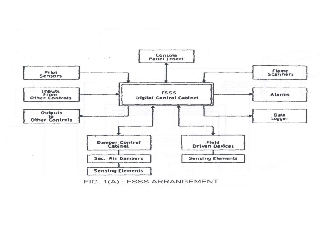
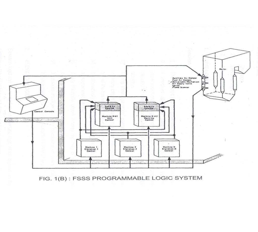

Arrangement of FSSS
- CONSOLE INSERT ON BOILER DESK
- FIELD EQUIPMENTS
- CUSTOMER SUPPLIED INTERFACE EQUIPMENTS
- SOFWARE SYSTEM
Field Equipment
- Gun nozzle valves
- Header trip valves
- Gun advance/retract mechanism
- Pulverizer discharge valves
- Hot air gates
- Secondary damper drives
- Flame scanner head assembly
- Local gun maintenance switch
- Signal initiating devices
Critical supplies for FSSS
- 220 V AC Supply
- 220 V DC Supply
- +24/48 V DC Supply
Organization of FSSS
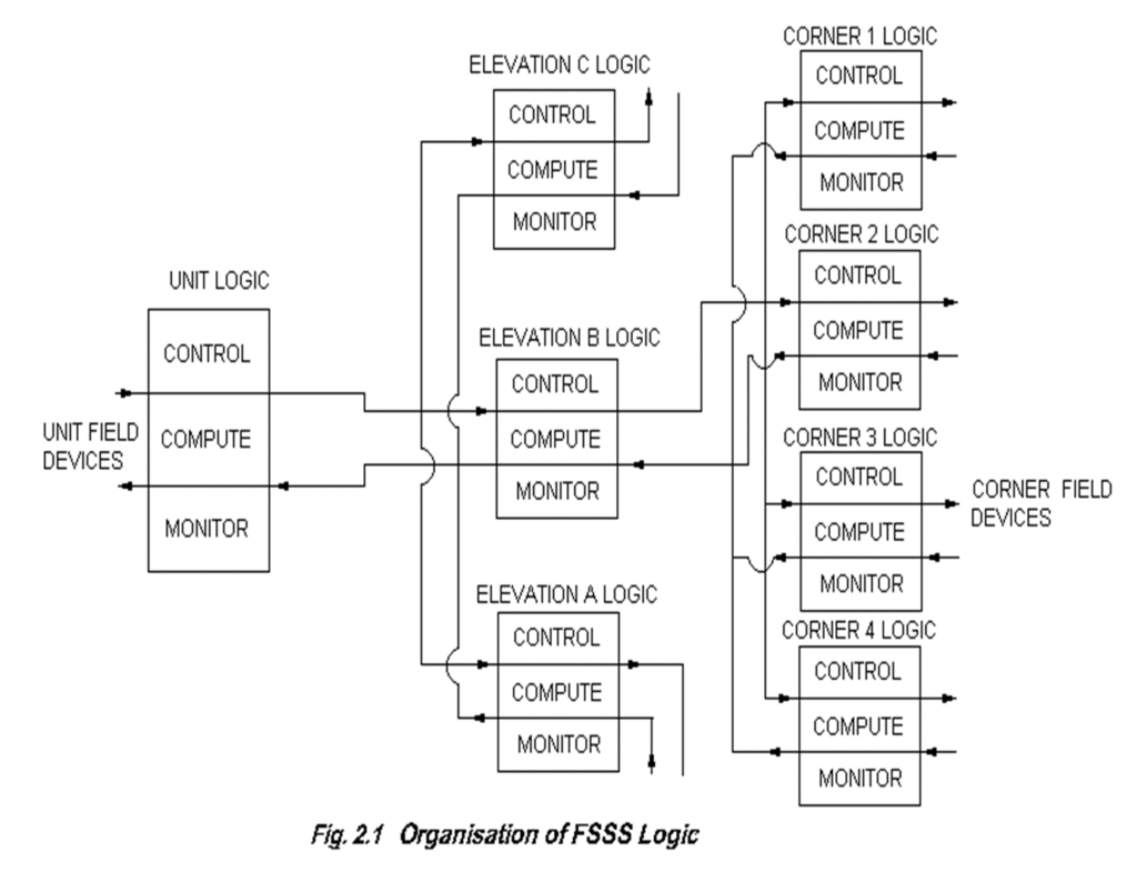
FSSS is functionally divided in 3 Groups
- UNIT LOGIC
- ELEVATION LOGIC
- CORNER LOGIC
UNIT LOGIC
- THE UNIT LOGIC SUPERVISES OVERALL FURNACE CONDITION.
- IT MONITERS ALL CRITICAL PARAMETERS OF FUEL FIRING SYSTEM.
- SUPERVISES FURNACE PURGE.
- EXAMINES ALL PERTINENT CONDITIONS REQUIRED FOR SAFE WARMUP BEFORE ALLOWING THE MAIN FUEL TO BE ADMITTED.
- WHEN BOILER IS ON LOAD THE UNIT LOGIC CONTINUOUSLY MONITORS CRITICAL FEEDBACKS TO ENSURE MAXIMUM SAFETY AND WILL TRIP ALL FUEL WITHIN PRESET TIME LIMIT. IT PROVIDES INTELLENGENCE TO THE OPERATOR ON OVERALL STATUS OF FURNACE AND INITIATE ALARM IF CONDITION WARNS.
ELEVATION LOGIC
THE ELEVATION LOGIC IS AN INTERMIDIATE LOGIC WHICH DEPENDS ON THE OPERATOR OR THE UNIT LOGIC FOR INITIATION OF START OR STOP ACTIONS. IT PROVIDES ESSENTIAL TRIP COMMANDS TO THE CORNER LOGIC.THE ELEVATION LOGIC IS DESIGNED TO SUIT THE TYPE OF FUEL IT CONTROLS. FOR EX. IF IT IS DESIGNED FOR PULVARISED FUEL, THE LOGIC ELEMENTS WILL BE DESIGNED TO SUIT THAT PARTICULAR PULVARISER AND ASSOCIATED EQUIPMENT LIKE FEEDER, HOT AIR GATE, PA FAN ETC. IN CASE OIL FIRING CORNER SEQUENCING ARE PERFORMED BY RESPECTIVE ELEVATION LOGIC. IN GENERAL ELEVATION RECEIVES COMMANDS FROM THE UNIT LOGIC OR THE OPERATOR WHEN TO START OR SHUT DOWN OR TRIP ELEVATION. IT PROVIDES FEEDBACK TO THE UNIT GLOG ON ACTIONS TAKEN BY THE ELEVATION LOGIC
CORNER LOGIC
- THE CORNER LOGIC DEPENDS ON ELEVATION LOGIC COMMANDS FOR INITIATION OF AN ACTION.
- DURING MANUAL OPERATION, THE CORNER LOGIC COMPUTES ITS OWN PERMISSIVES BASED ON IGNITION ENERGY AVALABILITY, STATUS OR VARIOUS CORNER DEVICES AND OTHER FACTORS FOR SEQUENCING OF INDIVIDUAL FUEL, AIR, OR STEAM VALVE OPERATIONS.
Furnace Purge
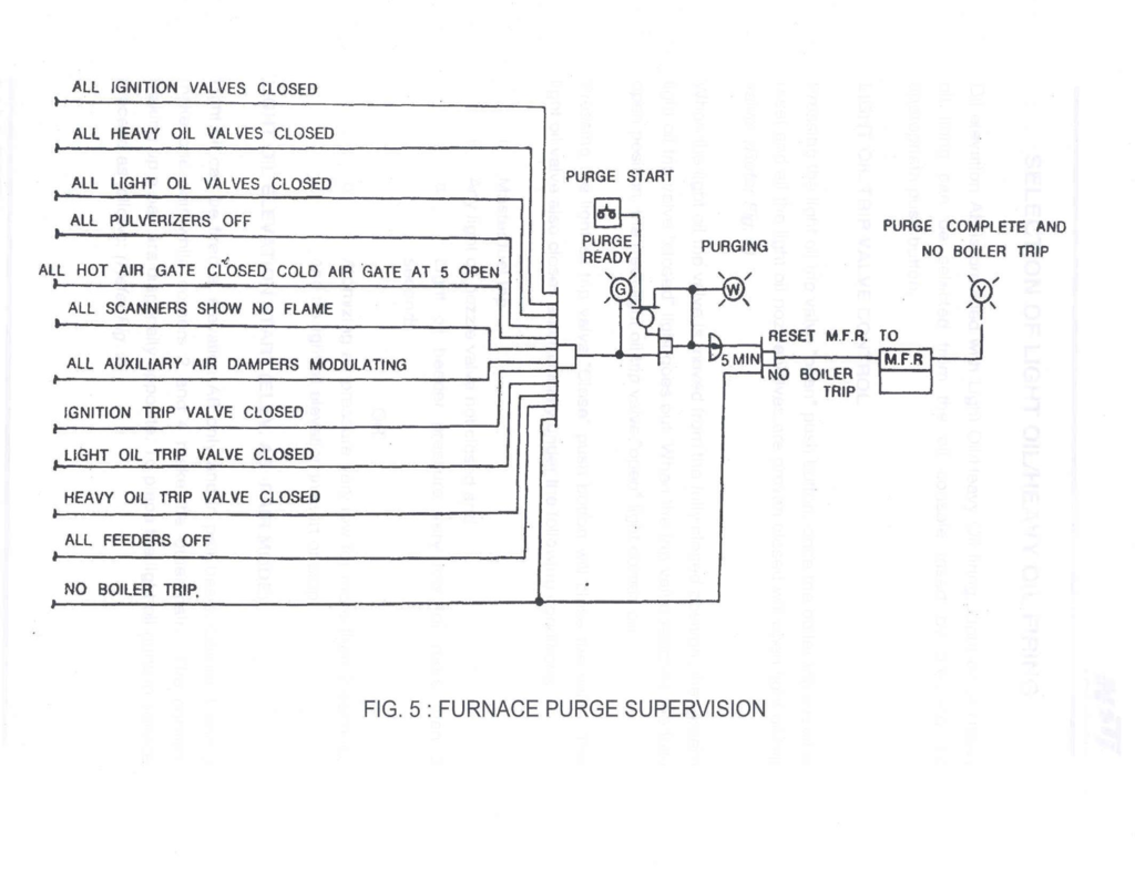
- Before any fuel firing can take place, (initially or after a boiler trip) furnace purge cycle must be completed.
- To start furnace purge cycle proceed as follows
-Establish AC and DC power to the FSSS panel at the related equipment
-Establish proper drum water level
-Place at-least one ID and one FD fan in service
-Establish a minimum at 30% MCR air flow through the furnace.
Depress the purge start push button for purging.
Purge permissive
(a) The light oil trip valve is proven closed
(b) All the light oil nozzle valves are proven
closed
(c) The heavy oil trip valve is proven closed
(d) All the heavy oil nozzle valves are fully
closed
(e) All PA fans off
(f) All feeders are off
(h) All pulverizers are off
(i) All the flame scanners show “No Flame” (both fire ball and discriminating scanners)
(j) No boiler trip command is present
(g) All hot air gates are fully closed
Light Oil Trip Valve Control
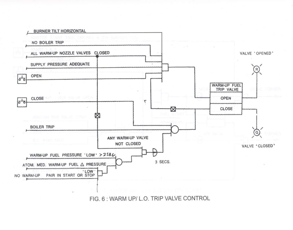
- Pressing the light oil trip valve “close” push button will close the valve.
- The light oil valve also closes automatically under the following conditions:
i) Master fuel trip
ii) Any light oil nozzle valve not closed and
(a) Light oil header pressure very low for more than 2 seconds(Low alarm-2.5kg/cm2 & 2.1kg/cm2 v.low trip)
OR
(b)Atomising air pressure very low for more than 2 seconds and no light oil elevation in start or stop.(Low alarm-4kg/cm2 & 2.1kg/cm2 v.low trip)
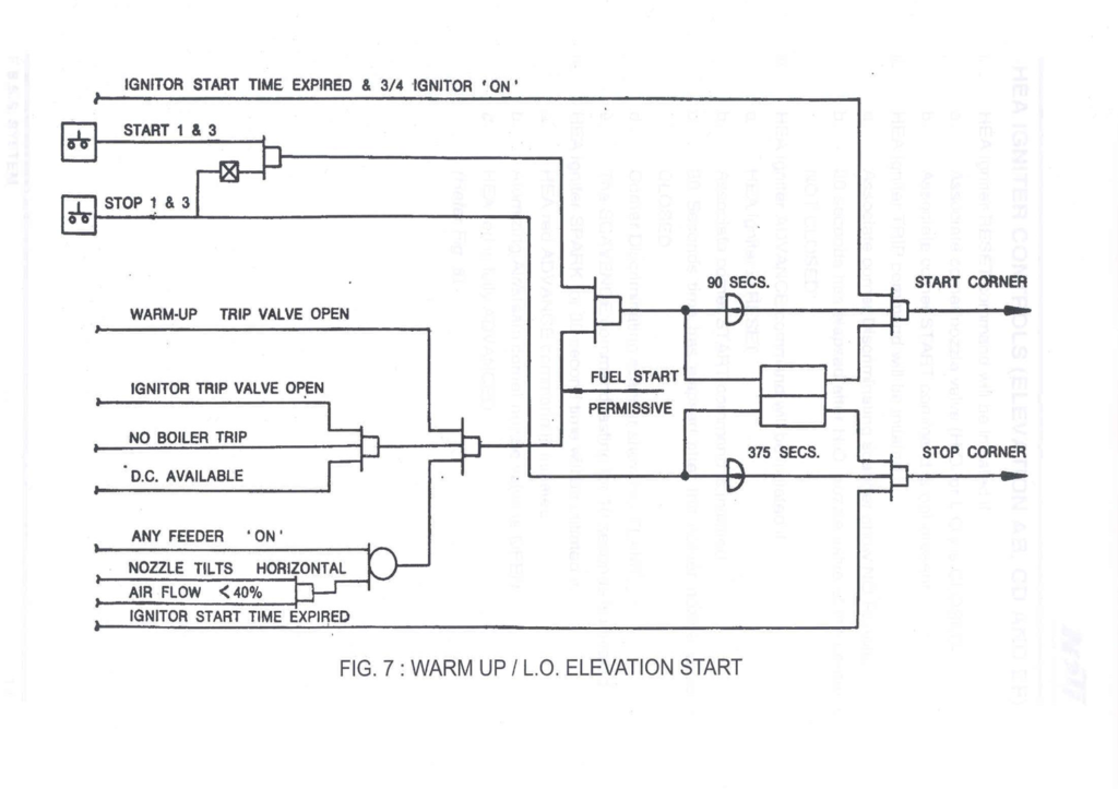
Light Oil Elevation Start (Elev. AB – Pair Mode)
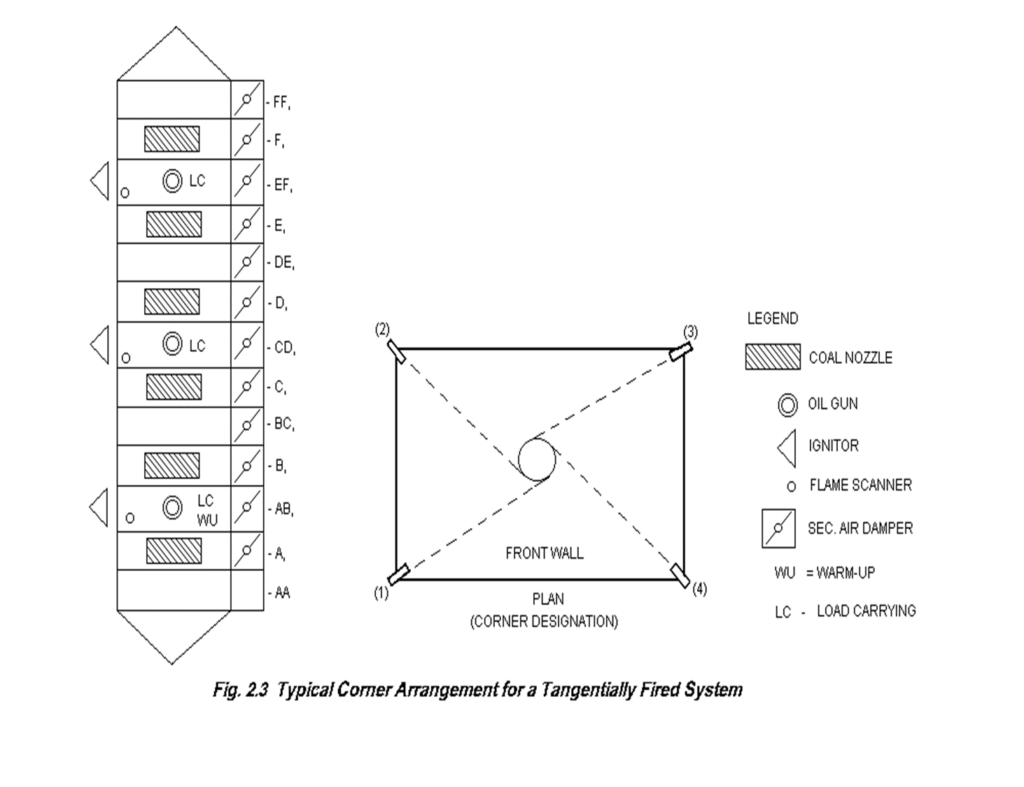
- Light oil can be fired at elevation AB only and in pair basis.
- Corner 1 and 3 make one pair while corners 2 and 4 make the other pair.
- The corners making up a pair are diagonally opposite.
- To place the light oil guns in service proceed as follows :

- Select light oil firing
- Establish light oil elevation start permit by the following conditions being satisfied:
- No master fuel trip
- Light oil trip valve proven fully open
- Air flow adjusted between 30% to 40%
- MCR
- Burner tilt horizontal
At each corner to be placed in service see that the following are satisfied:
- The oil gun is properly positioned at firing position
- Local oil gun maintenance control switch is in “Remote” position
- Light oil manual isolation valve is open
- Atomizing air manual isolation valve is open
Pressing the associated pair start (1-3 or 2-4) push button provided the above conditions satisfied will initiate a 90 seconds start trial time to place the associated pair of light oil guns in service.
Light oil elevation trip occurs under any of the following conditions:
(a) Master fuel trip
(b) Light oil trip valve not open
(c) Loss of unit critical power (+24V)
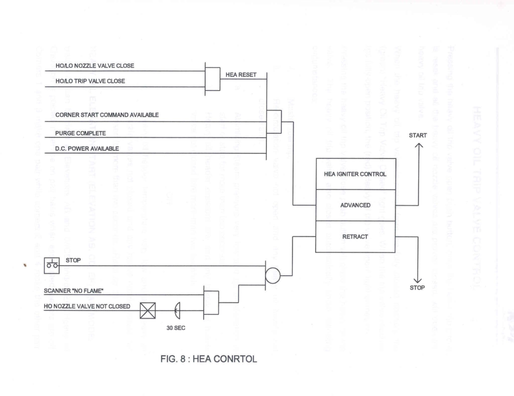
Heavy Oil Trip Valve Control
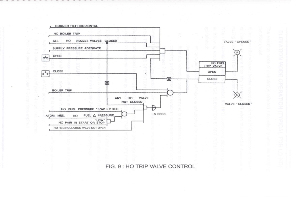
The heavy oil trip valve also closes automatically under following circumstances:
i) Master fuel trip
ii)Recirculation valve not open and any heavy oil nozzle valve not closed and :
(a)Atomizing steam pressure very low and no oil elevation in start or stop for more than two seconds(5.25 kg/cm2 low alarm,2.5kg/cm2 very low trip)
OR
(b)Heavy oil header pressure low and any heavy oil nozzle valve not closed for more than two seconds(3.5 kg/cm2 low,3.0kg/cm2 very low trip)
OR
(c)Heavy oil header temperature very high and any heavy oil nozzle valve not closed for more than two seconds(105 deg C alarm,90 deg C very high trip)


Seal Air Fan Control
- Seal air system has 3 seal air fans.
- Before cutting in the first mill, at least one seal air fan should be started manually by depressing the start push button. Before cutting in the fourth mill, the second seal air fan should be started.
- Once any one seal air fan has been started, and still the seal air pressure is low for more than 10 seconds,the second fan gets start command automatically.
If fan A gets a start command but does not start, after 5 seconds fan B gets start command.
If fan B gets a start command but does not start, after 5 seconds fan C gets start command.
If fan C gets a start command, but does not start, after 5 seconds fan A gets start command.
If any one of the two running seal air fans trip or the seal air header pressure is low and the third seal air fan does not start the mills will get trip command from top downwards.
Manual trip is possible only if the pressure is not low and :
(a)2 or 3 seal air fans on and less than 4 mills are in service
(b)1 seal air fan and no mill is in service
Each seal air fan has an associated outlet damper. Whenever any seal air fan is started, the outlet damper gets a close command. After 10 seconds, it gets an open command. Whenever, a seal air fan is stopped the associated outlet damper gets a close command.
PA Fan Control
The PA fan ready condition has to be established before starting the PA fan.
PA fan permissives are
- No MFR Trip
- Pulverizer Ignition permit available
- Hot air gate is closed
- Both Journal and Reducer seal air DP not low
- PA fan inlet damper is closed
PA Fan Tripping
The running PA fan will trip if anyone of the following conditions exist:
- PA Fan “OFF” push button depressed.
- MFR Trip
- Pulverizer Trip
- PA Fan Auto stop command initiated
- The Seal air-valve will get close command when all the following conditions are preset:
(i) Hot air gate closed
ii) PA Fan inlet damper closed
iii) CAD less than 5 % open
iv) Pulveriser off
v) Hot air damper closed
vi) PA fan is off
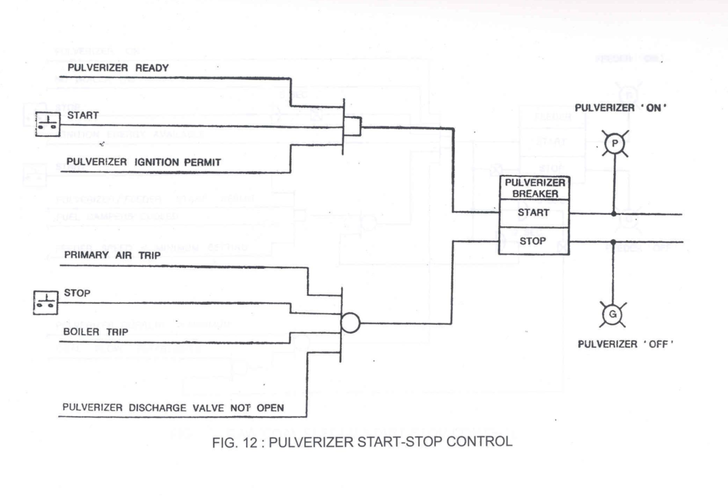
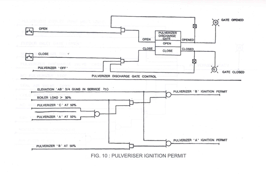
Pulverizer Ignition Permit
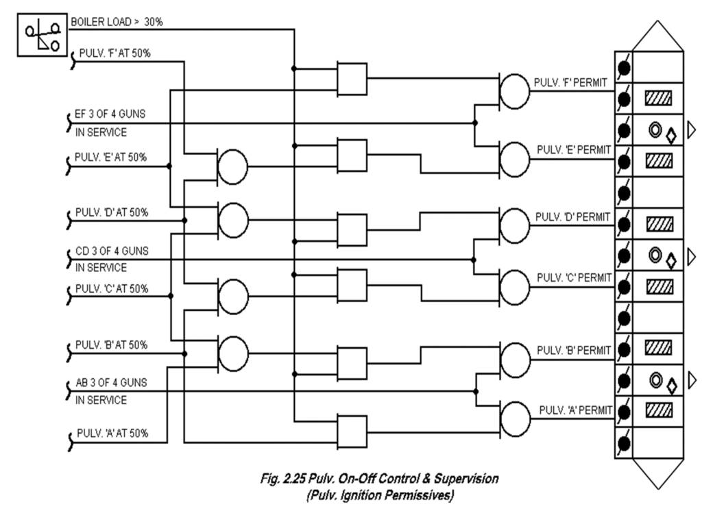
- Prior to starting any pulverizer, the pulverizer ignition energy must be adequate to support coal firing. This is accomplished as follows
Pulverizer ‘A’
(a) A minimum of 3 out of the 4 elevation AB Heavy oil nozzle valves proven open,
OR
(b) Boiler loading greater than 30% and pulverizer B is in service at greater than 50% loading
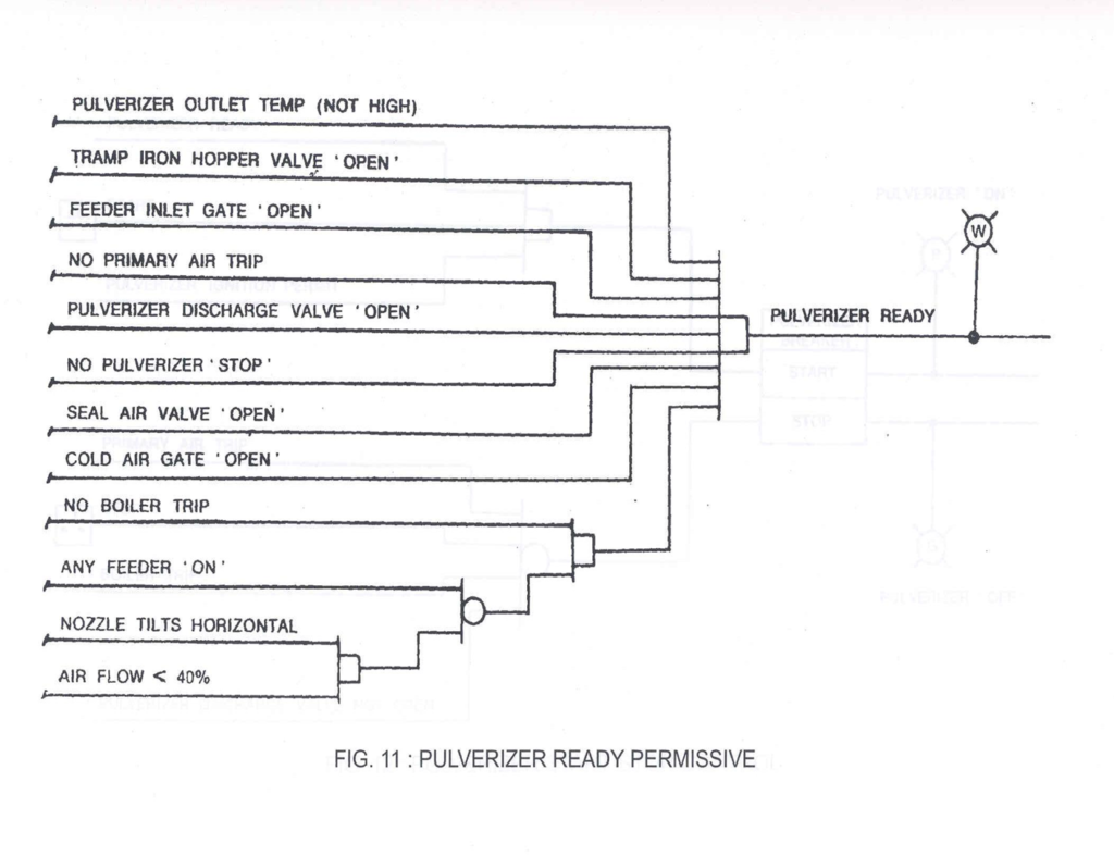
Pulverizer Ready
- Pulverizer must be established by confirming the following conditions being satisfied.
(a) D.C. Power available (+24V).
(b) Nozzle tilts placed in horizontal position
(c) Air flow adjusted between 30% to 40% MCR
At the respective pulverizer, following conditions are to be satisfied
Puvariser ready conditions
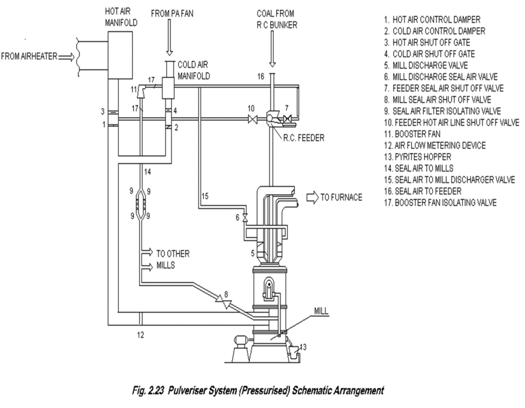
- Pulverizer discharge valve open
- Pulverizer outlet temperature (less than 94 deg. C)
- Cold air gate open
- No Pulverizer trip command
- Tramp iron hopper valve open
- Feeder inlet gate open
- PA fan on
- Pulverizer/Feeder start permit
- Seal air dp. 8″ WC or 200 mm WC
- All burner gates open
- No Auto Pulverizer unsuccessful start
- Lubrication oil permissives O.K.
- Pulverizer ignition permit available
Pulverizer ready indication appears
Pulverizer Trip Signals
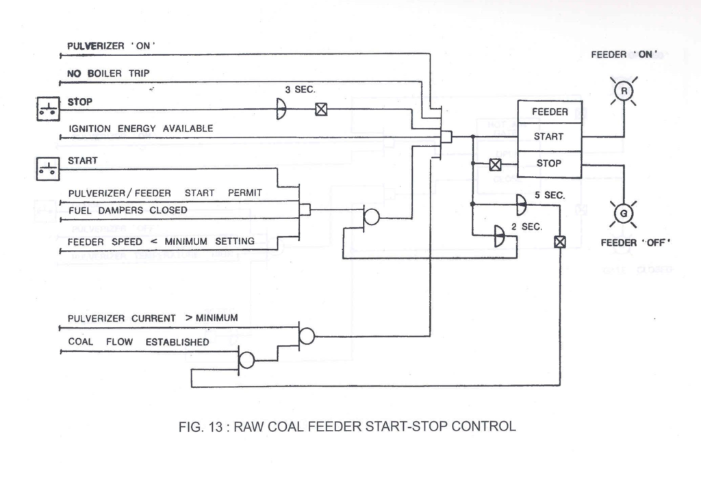
Any of the following conditions will give signal to run the feeder speed to minimum until the initiating condition is corrected.
-Pulverizer bowl differential pressure high
-Pulverizer motor current above maximum set point (MCR)
- Loss of coal flow and low pulverizer motor current will trip the feeder and closes hot air gate. (LCR)
- The operator should take appropriate corrective action then re-open the hot air gate and restart the feeder.
- High pulverizer outlet temperature (above 94 degree C) will open cold air damper full and closes the hot air gate.
Pulverizer trip commands
- Pulverizer discharge valve not open or any burner gate not open
- Loss of unit critical power (+24V)
- Pulverizer ignition permit is not satisfied i.e. support ignition is removed and less than 3 out of the 4 associated oil guns not in service.
- MFT
- PA fan trip
- Any seal air DP low
- Loss of Elevation DC (+24V)
- Lube oil permissive not OK
When only one FD fan trips and four or more pulverizers are in service, trip command will be given, starting from the pulverizer serving the top most coal elevation, until the number of pulverizers remaining in service are reduced to three.
Master Fuel Trip
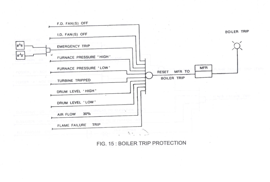
•The master fuel trip (MFT) is established when abnormal boiler conditions dictate that all fuel input to the boiler be removed immediately and automatically.
•The MFT command will be initiated by the following events.
MFT
- All ID fans off
- Both FD fans off
- Emergency Trip (initiated by the operator)
- Furnace pressure very low (-250 mm)
- Furnace pressure very high (325 mm)
- Re-heater protection trip
- Fuse failure in input modules connecting trip conditions.
- Drum level very high (+225 mm)
- Drum level very low (-225 mm)
- Loss of unit 220 V DC power for more than 2 seconds.
- Low air flow, i.e. air flow less than 30% while purging or when the unit load has not reached 30%.
- Unit flame failure trip
Elevation flame failure
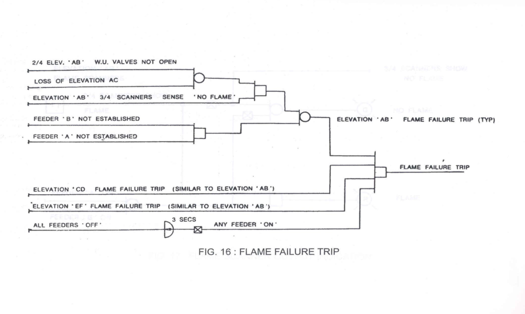
Elevation “A” Votes flame failure when any one of these conditions exist.
i) Feeder “A” not proven for more than 2 seconds
ii) 2 out of 4 H.O. or L.O. nozzle valves in elevation AB not open and fire ball scanners in elevation “AB” shows no flame.
iii)Elevation AB started and loss of elevation “AC” power for more than 2 seconds and elevation “AB” fire ball scanners show no flame.
First out cause of Trip System
- The first out cause of the trip is determined and displayed on unit console insert (First out monitor).
- All subsequent trip commands to the first out trip system will be blocked. This first out indication disappears when purging is completed & MFT reset
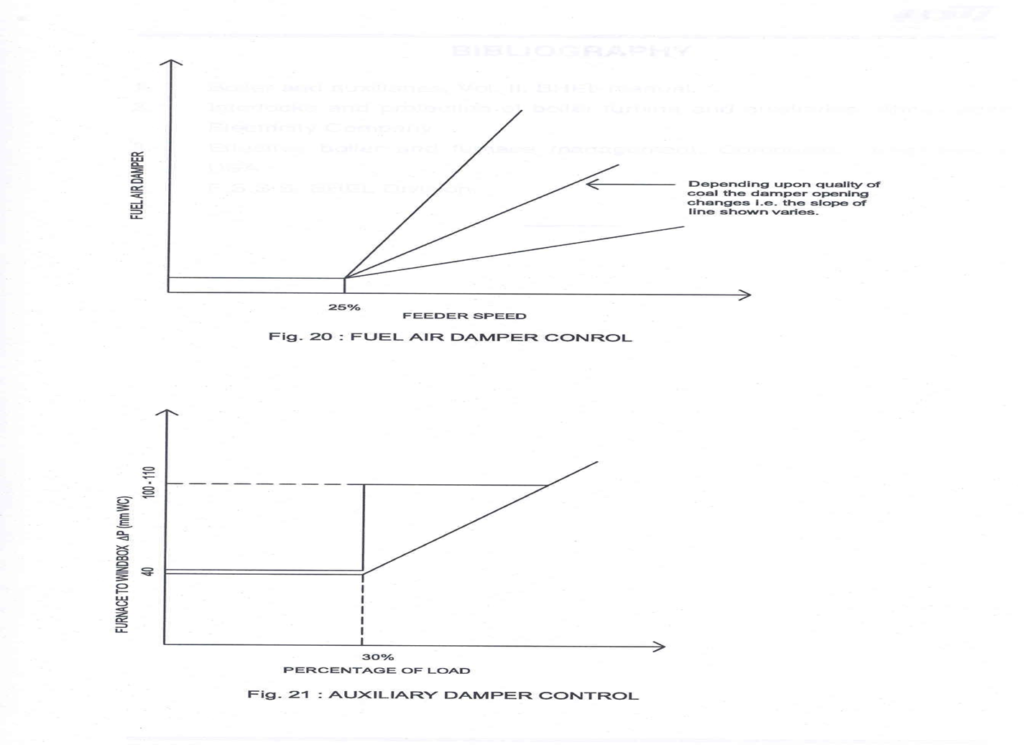
Secondary Air Dampers Control
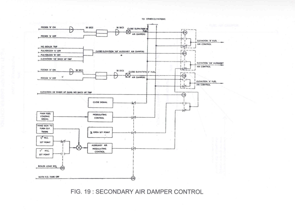
Auxiliary Air Dampers Control
All elevation of auxiliary air dampers will be automatically switched to “manual” control from “Auto” control and be commanded to open 100% when any of the following conditions exist.
- Both FD fans are off
- Both ID Fans are off
- A “Master Fuel Trip” condition exist for more than two seconds
- Unit critical power is lost for more than two seconds.
Fuel Air Damper Control
All elevations of fuel air dampers are commanded to open 100% when any of the following conditions exist:
- Both F.D. fans are off
- Both I.D. fans are off
- A ‘master fuel trip’ condition exists for more than two seconds
- Unit critical power is lost for more than two seconds
