There are several types of encoders used in motors to provide position feedback and enable precise control. The choice of encoder depends on factors such as required resolution, accuracy, speed, and environmental conditions. Here are some common types of encoders used in motors:
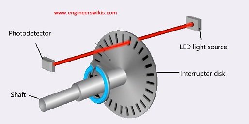
- Optical Encoders: Optical encoders use a light source, typically an LED, and a photoelectric sensor to detect patterns or markings on a rotating disc. The disc may have reflective or transmissive markings, and as the disc rotates, the changes in the light pattern are detected to determine the position or speed. Optical encoders can offer high resolution and accuracy, making them suitable for applications that require precise position control.
- Magnetic Encoders: Magnetic encoders use magnets and magnetic sensors, such as Hall effect sensors, to measure the rotation of a magnetic disc or magnetic poles on a rotating shaft. The magnetic field changes detected by the sensors provide position and speed information. Magnetic encoders are often chosen for their durability, resistance to dust and contaminants, and suitability for harsh environments.
- Capacitive Encoders: Capacitive encoders rely on changes in capacitance to detect position. They use electrodes and a dielectric material to form a capacitor. As the rotor rotates, the capacitance changes, providing position information. Capacitive encoders offer high resolution, immunity to environmental factors like dust or moisture, and can be used in both linear and rotary motion applications.
- Inductive Encoders: Inductive encoders utilize inductive sensing principles to measure position. They consist of a coil and a metal target. As the target moves, it induces changes in the coil’s inductance, which can be used to determine position. Inductive encoders are known for their robustness, resistance to environmental conditions, and suitability for high-speed applications.
- Resolver: A resolver is an electromechanical device that converts rotational information into electrical signals. It consists of a rotor and a stator with windings. By measuring the voltage induced in the stator windings, the position and speed of the rotor can be determined. Resolvers are commonly used in applications that require high reliability, durability, and resistance to extreme environmental conditions.
- Sin/Cos Encoders: Sin/Cos encoders, also known as sine/cosine encoders or resolver-based encoders, combine the principles of resolvers and digital encoders. They use resolver-like technology to generate a sine and cosine signal, which is then converted into digital position information. Sin/Cos encoders offer high accuracy, resolution, and reliability, making them suitable for demanding applications.
Some motors come with built-in encoders, known as integrated encoders or motor encoders. These encoders are directly integrated into the motor housing, providing a compact and efficient solution for position feedback.
The selection of the appropriate encoder for a motor depends on the specific requirements of the application, including resolution, accuracy, speed, environmental conditions, and cost considerations. Consulting with motor manufacturers or encoder suppliers can help determine the most suitable encoder for a particular motor application.
When choosing an encoder for a motor, several factors should be considered to ensure it meets the requirements of the application. Here are some important factors to consider:
- Resolution: The resolution of the encoder determines the smallest incremental position change it can detect. It is typically specified in terms of counts per revolution (CPR) or pulses per revolution (PPR). Higher resolution encoders provide finer position control but may require more processing power and have higher costs.
- Accuracy: The accuracy of the encoder refers to how closely it measures the actual position of the motor. It is important to select an encoder with sufficient accuracy for the desired level of precision in the application. Factors such as linearity, hysteresis, and thermal stability impact the accuracy of the encoder.
- Speed and Response Time: Consider the maximum speed at which the motor will operate and ensure that the encoder can provide accurate position feedback at that speed. Additionally, the response time of the encoder should be fast enough to keep up with the motor’s dynamic movements and provide real-time position updates.
- Environmental Conditions: Evaluate the environmental conditions in which the motor and encoder will operate. Factors such as temperature, humidity, vibration, shock, and exposure to dust or chemicals can affect the performance and durability of the encoder. Choose an encoder that is suitable for the specific environmental conditions of the application.
- Interface and Compatibility: Consider the interface and compatibility requirements of the encoder with the control system or motor driver being used. Common encoder interfaces include analog (e.g., voltage or current output), digital (e.g., quadrature, serial protocols), or fieldbus interfaces (e.g., CAN, Profibus). Ensure that the encoder’s output signals are compatible with the control system or motor driver to enable seamless integration.
- Mounting and Size: Evaluate the physical constraints of the motor system, including available space for mounting the encoder. Consider the size, form factor, and mounting options (e.g., shaft-mounted, flange-mounted) of the encoder to ensure proper installation and compatibility with the motor.
- Cost: Cost is an important consideration in any system design. Assess the budget constraints and balance the required performance and features of the encoder with the available budget.
- Application Requirements: Understand the specific requirements of the motor application. Different applications may have unique demands for position accuracy, speed control, noise immunity, and other factors. Select an encoder that aligns with the specific needs and performance criteria of the application.